I can say from meeting you and watching your contributions that you're the guru on all things electrical Ps, bravo! And thanks for your efforts, I'm sure they'll pay off somewhere to someone!
For the time being I've focused mainly on CDI boxes. Sadly this info isn't presented very well in the wire diagrams in the service manuals, so I've been wanting to document this data in some fashion for a while now. Since I make harnesses, I have a fair collection of harnesses from 3 wheelers, and they are my primary reference for pinouts when reproducing them, I want to make that process a lot easier on my self and also offer it up for others to use (maybe a website or something down the road). Wire colors for the most part seem standardized between machines, CDI pinouts on the other hand isn't as nice.
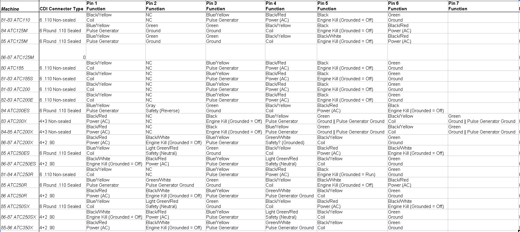
Not sure how this data will show up as a post, so I'll post it as an image. Data is formatted so I could import it into a data base Please point out anything that seems wrong.. I have most service manuals to track the function of each wire.
Note: Power AC vs DC is based on if the power from the stator is ran from the rectifier/battery, this might be poor logic on my part, so could be inaccurate. Also NC = no connection.
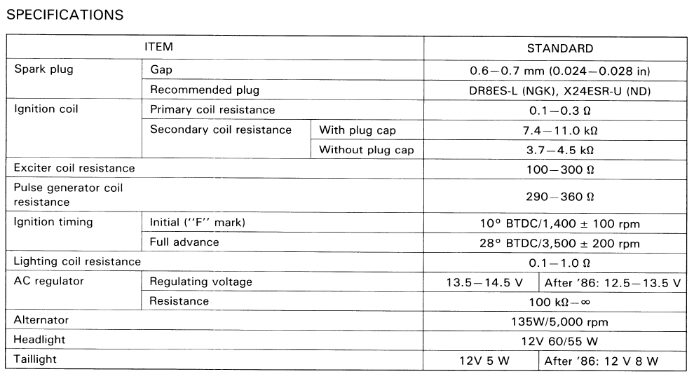
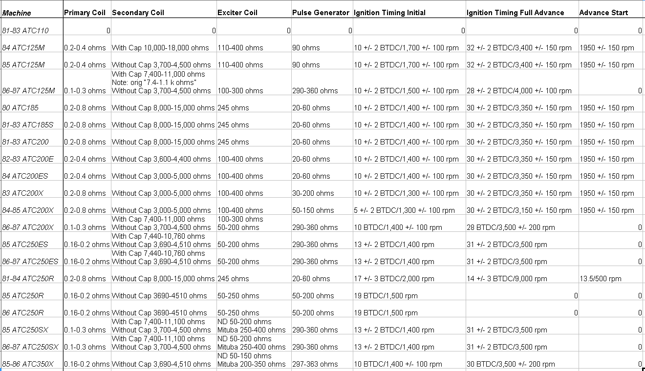
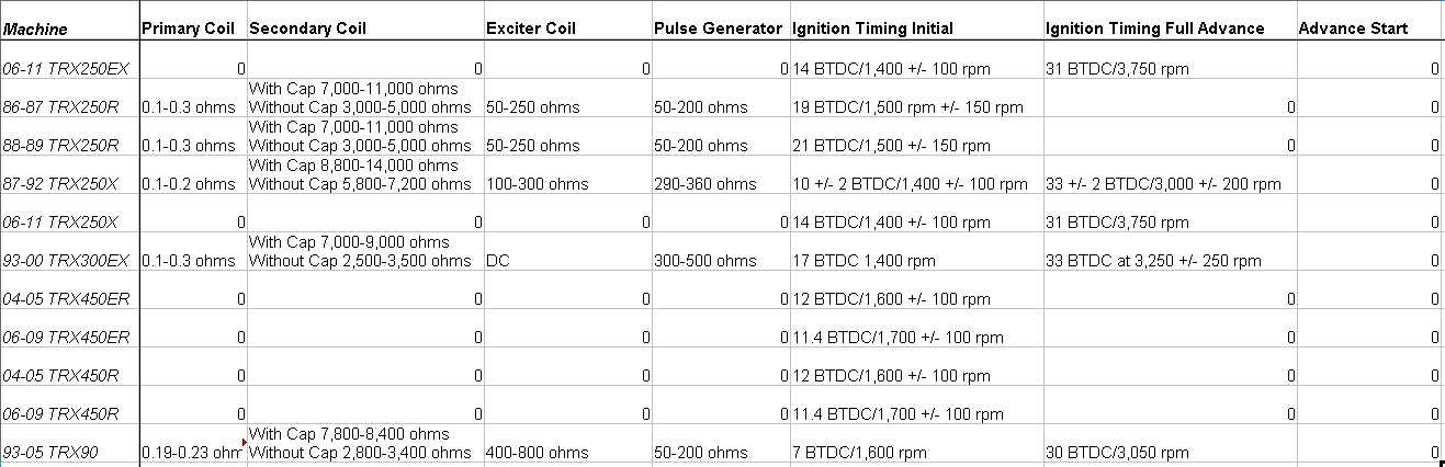
Ignition parts specs
Note: 0 means no data entered in the data source.
Some extra info that might be of interest, what CDI's match pinouts based on function. This list doesn't mean a CDI will 100% work within the groups, but could be an option to try.
4+2 style CDIs
86-87 ATC250ES (safety switch is on neutral)
86-87 ATC250SX (safety switch is on neutral)
87-82 TRX250X (safety switch is on reverse)
86-88 TRX200SX
86 ATC200S
86-87 ATC200X
86 ATC250R (2 stroke)
85-86 ATC350X
6pin rectangle style
81-83 ATC110
80 ATC185
81-83 ATC185S/200
82-83 ATC200E
81-84 ATC250R (2 stroke, also kill switch reversed operation unless service manual is wrong)
6pin round style
84 ATC200ES (safety switch is on reverse)
85 ATC250ES (safety switch is on neutral)
85 ATC250SX (safety switch is on neutral)
84-85 ATC110
84-85 ATC125M
86-87 ATC125M (safety switch is on reverse)
84-85 ATC200M
84-85 ATC200S
85 ATC250R (2 stroke)
4+3 pin style
83-85 ATC200X
Some data I'd like to get validated:
84 ATC110 - check if wire colors match 81-83 or 85 (mainly the black/white vs black wire)
86-87 ATC125M - check if CDI connector is 4+2 style or not. If it is I need the pinout colors
Hopefully this useful proves to be useful to someone besides myself =). Also attached photos are to show what my fancy pin numbers mean.
Last edited by ps2fixer; 10-29-2018 at 04:57 AM.
I can say from meeting you and watching your contributions that you're the guru on all things electrical Ps, bravo! And thanks for your efforts, I'm sure they'll pay off somewhere to someone!
Trikes
1970/71 US 90 (Aquarius Blue)
1970/71 US 90 (Future Resto Project)
1972/73 US 90 Camo Project (110 Big Bore)
1972/73 US 90 Green
1977 ATC 90 w/83 110 motor (Fugly)
1982 ATC 70
1983 ATC 70 (Ladybug)
1973 ATC 70
1965 Marketeer 3 Wheel Golf Cart with 1986 Honda 250 drivetrain
TF 2015
Feedback http://www.3wheelerworld.com/showthr...ck-for-coopool
http://www.3wheelerworld.com/showthr...k-for-coolpool
Thanks for the kind words coolpool. Figured if I'm going to put the effort together to make some sort of webpage/site/database for my self, why not release it for everyone with a little more dev work.
It's kind of funny, I can scan though a Honda wire diagram really fast, same with a Toyota vehicle wire diagram, but as soon as I jump to say Yamaha, I can't follow them and I have to think about things more like if they are assuming the coil is grounded to the frame though the bolt or not etc. Talking about wire diagrams, I hope to recreate most wire diagrams in the service manuals myself so they don't get blurry when you zoom in and such. Tech term if vector graphics, but not sure if javascript or html5 supports that like Flash which is more or less blocked by everything today. Would love to make interactive wire diagrams where the layout matches the physical wire harness layout and you click like the green wire on the CDI and it shows everywhere the wire goes and of course a solid pinout of each connector. Just a thought I've had a couple years ago, just haven't really acted on it till now. Not sure what the end product will really end up being since I hope to make it easy to scale to include quads, side by sides, etc. In theory ads and/or product sales should cover the dev time building something like this if it actually becomes semi popular. Having user submitted data would be a huge perk/benefit but making the data easy to enter with minimum mistakes will be a real challenge.
Anyway, this CDI project is more targeted at "upgrade" options for the 85 and older models to use the 86+ 4+2 CDI connector and the added benefit of being much much more common (they fail less maybe?). Clear picks is the 85 250es/sx and the 85 250r since the later model CDI is known to work on them, but I suspect the coverage is broader than some might think. I suspect if there's a lot more data available, the CDI connector will be a more common upgrade, and of course I offer the pig tail so there's a bit of a business motive too but that's life in a nutshell.
Seems like I've been earning my title as "the wire harness guy" =D.
Very very nice!! Thank you for sharing, I printed it out!!
All our government does is distract us while they steal from us, misspend our tax $ and ruin our country
Don't forget to check back once in a while for updates. Got thinking lately, and resistance specs are kind of part of how the CDI will have to function for any interchange. Besides that it would help anyone with a no spark situation. Of course expanding the data too much really makes an interactive webpage kind of a requirement so one machine can be looked at, and the mass of info presented at once.
Also never thought of it before, but the CDI inspection process in the service manual where there's the table of values to test has the pinout. 81-84 ATC250R's are all the same pinout/spec =).
Ok found a bit of an issue one of the service manuals, maybe it's a mistake, or I'm not reading things correctly? This is from the Honda ATC200X 1986-1987 Service Manual, basically it gives 2 different specs for the exciter coil (see below). For now I'll just add both specs in my spreadsheet, not sure if I should combine the values or keep them separated. Makes me wonder what "off brand" service manuals say the spec is.
vs down a bit in the more detailed area....
Researching this a bit further and finding what all machines the exciter coil interchanges on, and first one comes up with a 85 250sx, which has two specs based on brand, and one of the specs matches the lower section (ND 50-200 ohms), so I guess that would be the accurate spec? I'll check the other machines too and see if that's the common spec among them. Have to love standardizing things =).
Edit, interesting, the TR200 Fat Cat uses it too, it's spec in both spots is 100-300 ohms, but it gives an extra spec, temp, 20c/68f. Maybe that's hot vs cold spec since copper does change resistance with temp, if I recall correctly colder = lower resistance though...
Awesome info thanks for sharing!
Not a problem. It's all info contained in the service manuals which 99% of them can be found online free, but I know sometimes it's a pain to find the links or links die. Raw data/specs can't be copyrighted or taken down =).
Anyway, updated the first post with the extra data I started adding. Lot of blank area, but I'll fill it in as I run though things. I probably should sort the machines in some logical order like size in cc, model, then year. Next update I'll try to have it ordered a little better and probably a lot more complete.
I know Honda gets all the love on collecting info, but if I can dig up the details etc, I'll do my best to include the other brands as well. I can read the Honda wire diagrams the best, so that's why I target them first in almost everything I do.
Been digging a bit to see if I can find any CDI's that match the same specs as these older engines, and the newer stuff is somewhat similar, but the specs of the other components are higher resistance (higher voltage). I did come across http://ricksmotorsportelectrics.com which seems to have a CDI for nearly all models except some 85 models that I know use the round 6 pin connector. Their interchange seems to match OEM part number interchange too. Not sure if the company is well known or not, but might suggest them for those that want to upgrade their CDI connector to the 4+2 style. Would be awesome to hear some feedback on their products if anyone has experience.
Last edited by ps2fixer; 10-27-2018 at 01:59 AM.
Found another mistake in the Honda service manuals lol, this time for the 1985 ATC250es big red. Based on my diagrams above, CDI pin 1 is marked as Black/Yellow in their photo for the PC pin, but in their table for testing it, it's Blue/Yellow. Blue/Yellow would be the correct color and also matches the wire diagram.
Not really the best way to log service manual mistakes, but atleast it's somewhere encase someone searches it lol.
Fun fact, 250es and 250sx do have the same base/max spark advancement, so seems like they should be the ideal interchange between each other. I haven't finished the pin outs yet, but from what I've read they do interchange. That also goes for 85 vs 86-87, only difference being the connector used.
Here's a pic of the differences, 86-87 specs seem to match fine, only the 85 data was wrong in the CDI pic.
![]()